Errors in the Design of Fire Ventilation Automation Systems
The fire ventilation system in buildings is responsible for life safety, enabling access for emergency services, and protecting property. The principle of correct system operation is to direct smoke flow and remove harmful combustion products outside the building. For this purpose, already at the design stage, smoke and heat control systems, electrical installations, and fire detection and alarm systems should be integrated with one another.
The coordination of the proper operation of these systems and installations is ensured by power supply and control units forming part of smoke and heat control systems. The correct selection of the fire automation arrangement is one of the most important stages in designing a fire ventilation system. This article presents the most common design errors related to the power supply and control units of mechanical smoke extraction systems.
Lack of interdisciplinary coordination
The issue of fire automation requires close coordination between disciplines, above all between the electrical and sanitary engineering disciplines. The vast majority of design errors concerning power supply and control units for fire ventilation systems are directly related to a lack of interdisciplinary coordination.
Lack of a fire ventilation system automation design
At present, there is no regulation specifying whose scope of work includes the preparation of the design of power supply and control units for smoke extraction systems. This is a matter to be agreed between the architect and the discipline designers. In practice, the lack of a precise definition of the scope very often leads to the omission or superficial preparation of the smoke extraction automation design. The ventilation designer limits their work to passing on the electrical parameters of the selected fire ventilation system equipment to the electrical designer, and the electrical designer, on this basis, takes into account only the protection and the supply line from the fire switchboard. In this way, the design documentation becomes incomplete.
The design of the fire ventilation system automation arrangement should consist of:
- a block diagram including the range of devices powered, controlled and monitored by the designed units, the protective apparatus used for individual devices, and the cable selection;
- a power balance including a list of the electrical parameters of the devices powered and controlled from individual units, including: electrical power, rated voltage, rated current and starting current;
- a list of signals to/from the fire alarm system.
Due to the complexity of the issues directly related to electrical installations and automation, it seems justified that the above-mentioned design should be prepared by the electrical designer in consultation with the sanitary designer.

Failure to provide a technical specification
A lack of communication between sanitary and electrical designers results in incorrect assumptions being adopted in the electrical design. After selecting the complete set of devices for the fire ventilation system, the sanitary designer should provide the full list and technical specification to the electrical designer. This has a significant impact on the correct design of the electrical installation, including the selection of protections, the types and cross-sections of supply cables, cable routes, and even the selection of the building’s backup power supply.
Situations are very often encountered in which errors in the electrical design, resulting from a lack of communication between discipline designers, are detected at the construction stage. The most frequently recurring errors include:
- the selection of incorrect electrical protection for the power supply and control unit of the fire ventilation system, or the selection of an incorrect cross-section of the supply cable. Such errors result from failure to provide the electrical parameters of the selected fire ventilation system devices;
- an incorrect design of cable routes – an error arising from failure to provide information on the location of devices (e.g. jet fans);
- incorrect selection of backup power supply – an error resulting from failure to take into account the correct values of the starting currents of smoke extraction fans.
Cooperation and communication at every stage between discipline designers are very important and make it possible to avoid numerous irregularities.
Omission of important scopes – damper control
The issue of the fire ventilation system is very extensive and consists of many smaller scopes, the interaction of which is crucial for the correct operation of the system. The implementation of power supply and control for individual devices may take place in different ways, and in this case knowledge of the regulations is important.
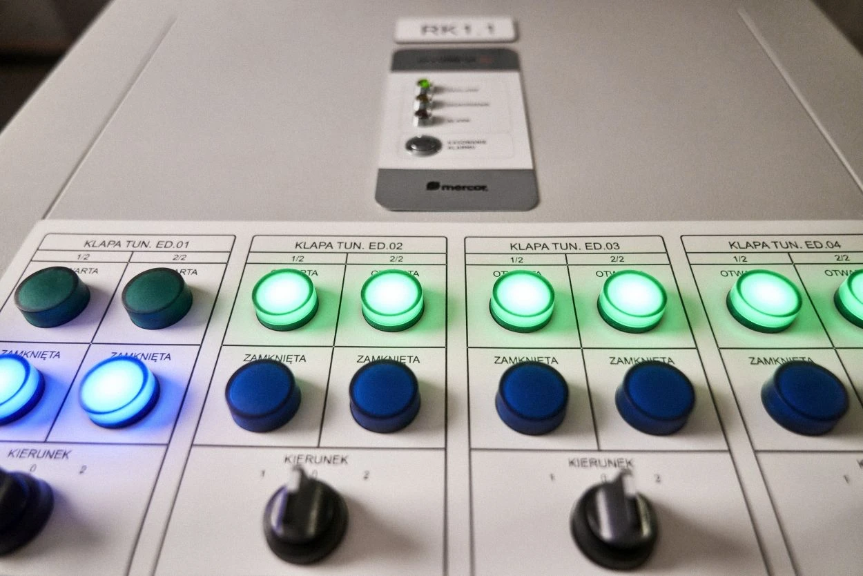
An example is the control of fire dampers in the fire ventilation system, i.e. the smoke extraction installation. In the low-current installation design, this scope is often rightly omitted. This follows directly from standard PN EN54-1:2011, which states that the task of the fire alarm control panel is solely to detect fire and transmit the alarm to external devices [1]. In such a case, damper control should be included in the power supply and control unit of the fire ventilation system, which meets the requirements of PN EN12101-9 and is therefore a device that can automatically activate measures intended to limit the effects of fire (opening/closing the fire dampers of the smoke extraction installation) [2].
Situations often occur in which the design of the fire ventilation control unit incorrectly assumes that the scope of damper control will be included in the design of the fire alarm system, and ultimately this area is omitted completely.
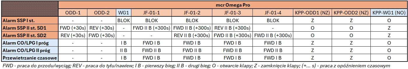
Lack of control guidelines – control matrix
The control matrix is a tabular statement presenting the operating method of fire ventilation system devices depending on fire signals. It is a document that consolidates the information contained in the fire scenario, CFD simulation, fire alarm system design, and fire ventilation design. The control matrix is the basic document enabling the correct prefabrication and programming of the power supply and control unit of the fire ventilation system.
It commonly happens that the control matrix is omitted entirely from the design, and the device manufacturer or installation contractor assumes responsibility for interpreting and integrating the provisions contained in the scenario, simulation, and discipline designs. Problems begin when the above-mentioned documents contain gaps that make it impossible to create a precise control matrix. This concerns, among other things, the absence of information about:
- the activation times of individual devices,
- the operating directions of jet fans,
- the required signals to/from the fire alarm system,
- the method of operation of fire dampers,
- the division into detection zones of the day-to-day ventilation system (in cases where the control unit is responsible for controlling the day-to-day garage ventilation).
Determining the details concerning control at the implementation stage significantly extends the installation process and sometimes delays final acceptance. Therefore, the control matrix should be a standard document included in the ventilation installation design.
Incorrect selection of fan protections
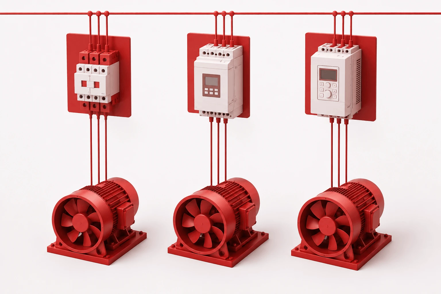
Power supply and control units for fire ventilation make it possible to use various starting arrangements for the motors of smoke extraction fans. These arrangements include: frequency converters (inverters), soft starters, direct-on-line starting, star/delta starting, and the Dahlander arrangement.
The selection of the correct protection depends on the purpose of the fan. This is one of the most important stages in designing a fire ventilation system control unit. Before proceeding with the selection of the arrangement, the purpose and operating method of the smoke extraction fan should be analysed in terms of reversibility, number of speeds, and operating point. Each arrangement is characterized by a specific starting current, which affects the building’s electrical installation.
The starting method that makes it possible to implement all required fan operating scenarios (except for jet fans) is the frequency converter, commonly referred to as an inverter. It is characterized by the lowest starting current (up to 120% of rated current). This is the safest starting method, the use of which does not require an in-depth analysis of the parameters of the electrical network and the operating method of the fan.
In the case of the remaining arrangements, it is best to contact the manufacturer of the power supply and control units, because their incorrect selection may entail negative consequences. A particular hazard is the selection of protection with a high starting current (direct-on-line starting, star/delta, soft start) without prior analysis of the parameters of the building’s electrical network and the designed electrical protections for the units.
It should also be remembered that the selection of specific starting methods affects the selection of the supply cables for the fans. Any optimizations or design changes in this respect require verification by the electrical discipline designer.

Use of a non-certified power supply and control unit
Power supply and control units in smoke and heat control systems should meet the requirements contained in standard PN-EN12101 (9 and 10) and in the Regulation of the Ministry of the Interior and Administration of 27 April 2010 on the list of products serving to ensure public safety or the protection of health and life and property, and on the rules for issuing approval for these products for use. Confirmation of this is provided by certification documents such as: the National Technical Assessment, the Certificate of Approval, and the Certificate of Constancy of Performance.
Awareness of the need to use certified solutions is growing among electrical installation contractors. However, in design studies it happens that the power supply of fire protection devices (e.g. smoke extraction fans or jet fans) is designed from electrical switchboards that meet only the requirements of the Low Voltage Directive (LVD) 2014/35/EU. In such a case, the automation arrangement is usually omitted, and the fire fan is treated as an ordinary electrical load. Such a design requires the issuance of a revision – including a certified power supply and control unit.
The design of power supply and control units for fire ventilation systems requires a multidisciplinary approach. Improper coordination between specialists in their respective fields may lead to irregularities and omissions in the design. This, in turn, may result in problems with the final acceptance of the building or in faulty operation of the system ensuring the safety of its users.
The Fire Ventilation Automation Department of Mercor Light&Vent sp. z o.o. provides assistance in design and support in solving problems. Please contact us at: automatyka@mercor.com.pl
Adrian Wyrzykowski
Senior Fire Automation Specialist
Fire Ventilation Systems Division
[1] Fire detection and fire alarm systems. Part 1: Introduction. PN-EN 54-1:2011
[2] Smoke and heat control systems; Part 9: Technical specifications for control systems for smoke and heat exhaust systems. PN-EN 12101